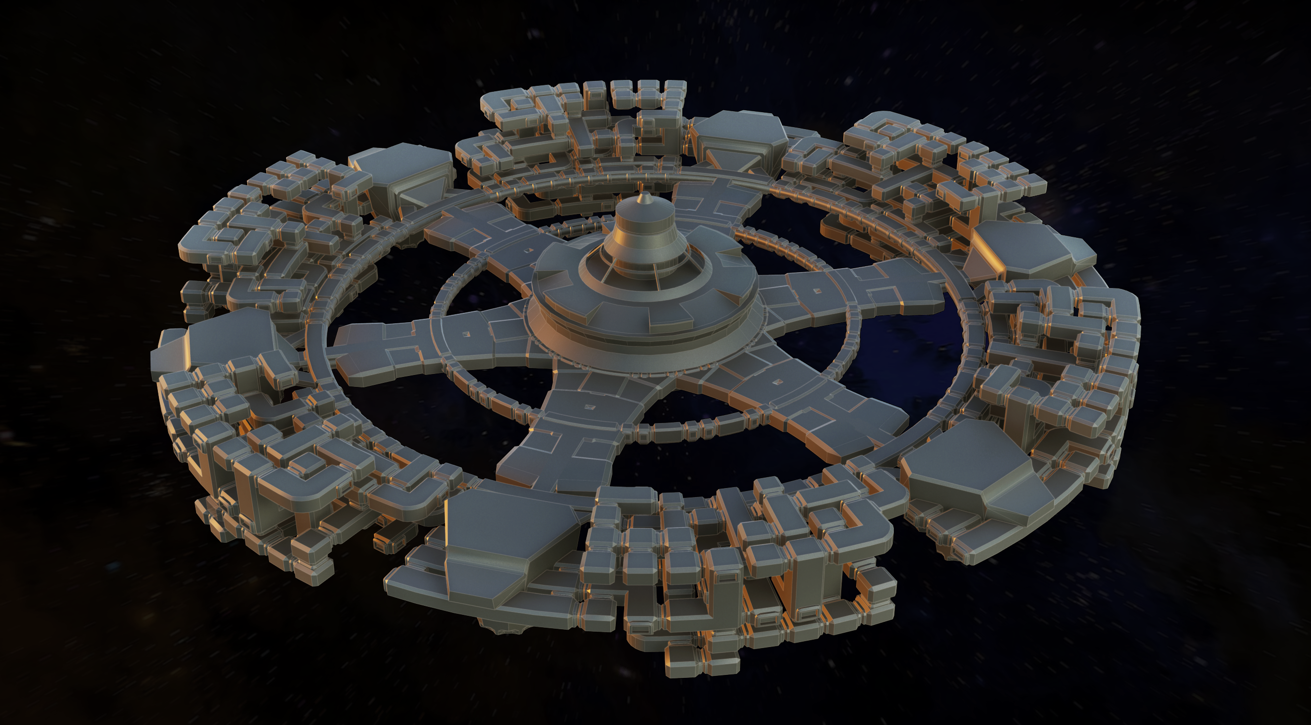
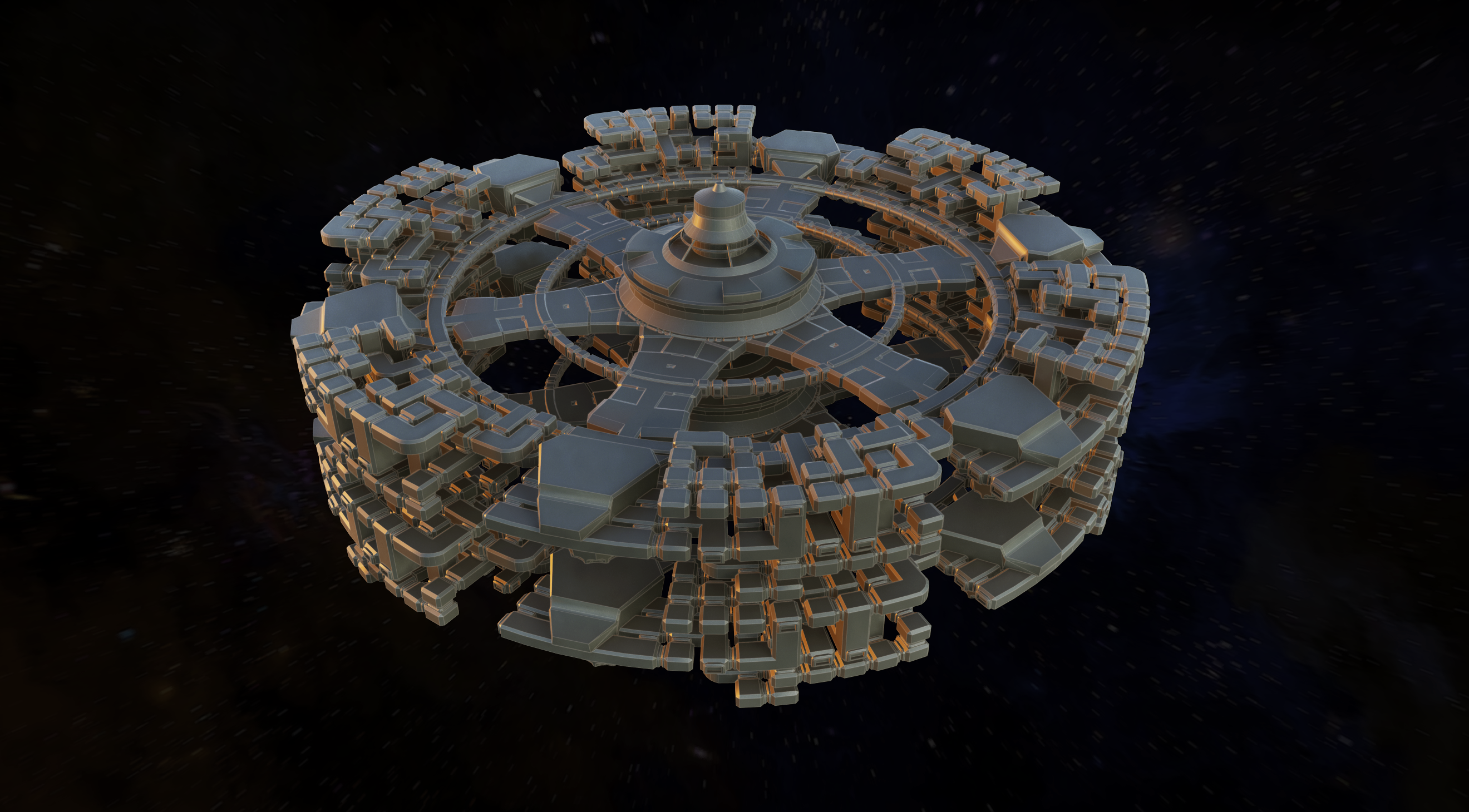
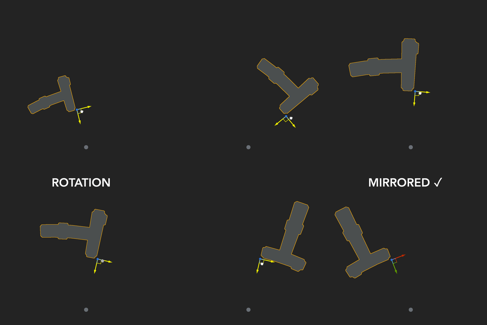
In my senior year, I began working on a city-builder that allows players to construct a modular space station in a circular layout, similarly to games like Frostpunk (2018) and Ixion (2022). During the pre-production phase, the building system involved placing each module on a circular construction grid, allowing players to orient the modules in one of four directions and mirror their shapes. My responsibilities included creating a specialized material function in Unreal Engine and establishing guidelines for the artistic pipeline.
POLAR GRID AND PRESERVING PROPORTIONS
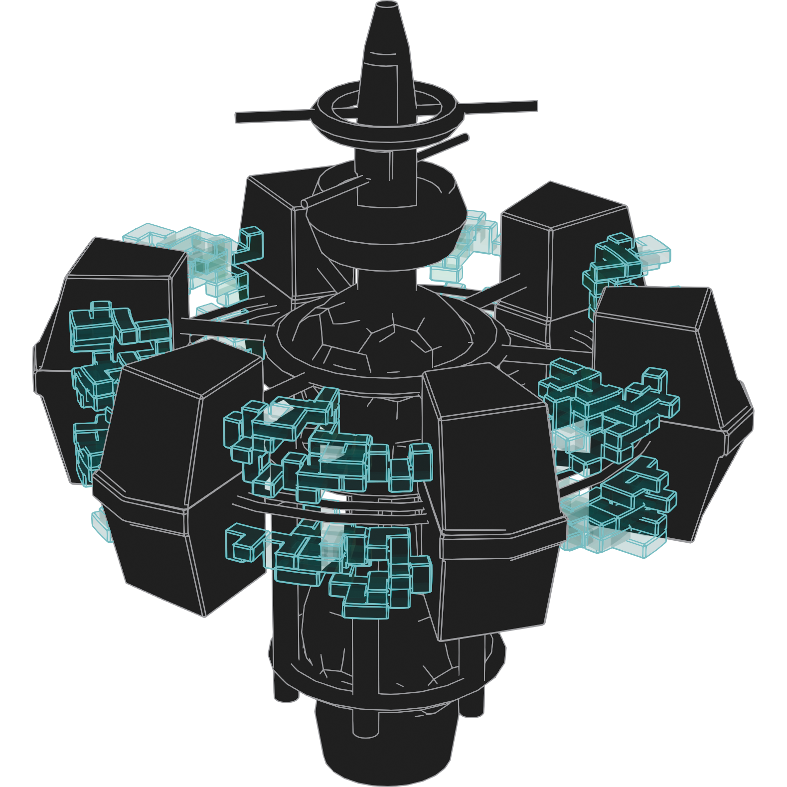
When using a polar grid to divide 3D space into equally spaced radii, there is a threshold radius value. Beyond this threshold, the grid cells expand, while below it, the grid cells contract. To maintain correct proportions, the grid must be adjusted so that the cells remain square beyond the threshold radius.
The threshold radius $r_0$ depends on $l_0$, the desired size of a grid cell at the threshold, and $N_\theta$, the number of angular steps of the grid: $$r_0=\frac{l_0 N_\theta}{2\pi}$$ To ensure the cells are square beyond $r_0$, the grid has to be stretched so that for $n\in\mathbb{N}$: $$r_n=r_0\left(1+\frac{2\pi}{N_\theta-\pi}\right)^n$$
Regular
Proportions are maintained only at $r_0$, so the blue-shaded acceptable region is only one cell thick.
Stretched
After stretching the grid, the region where proportions are preserved extends infinitely beyond $r_0$.
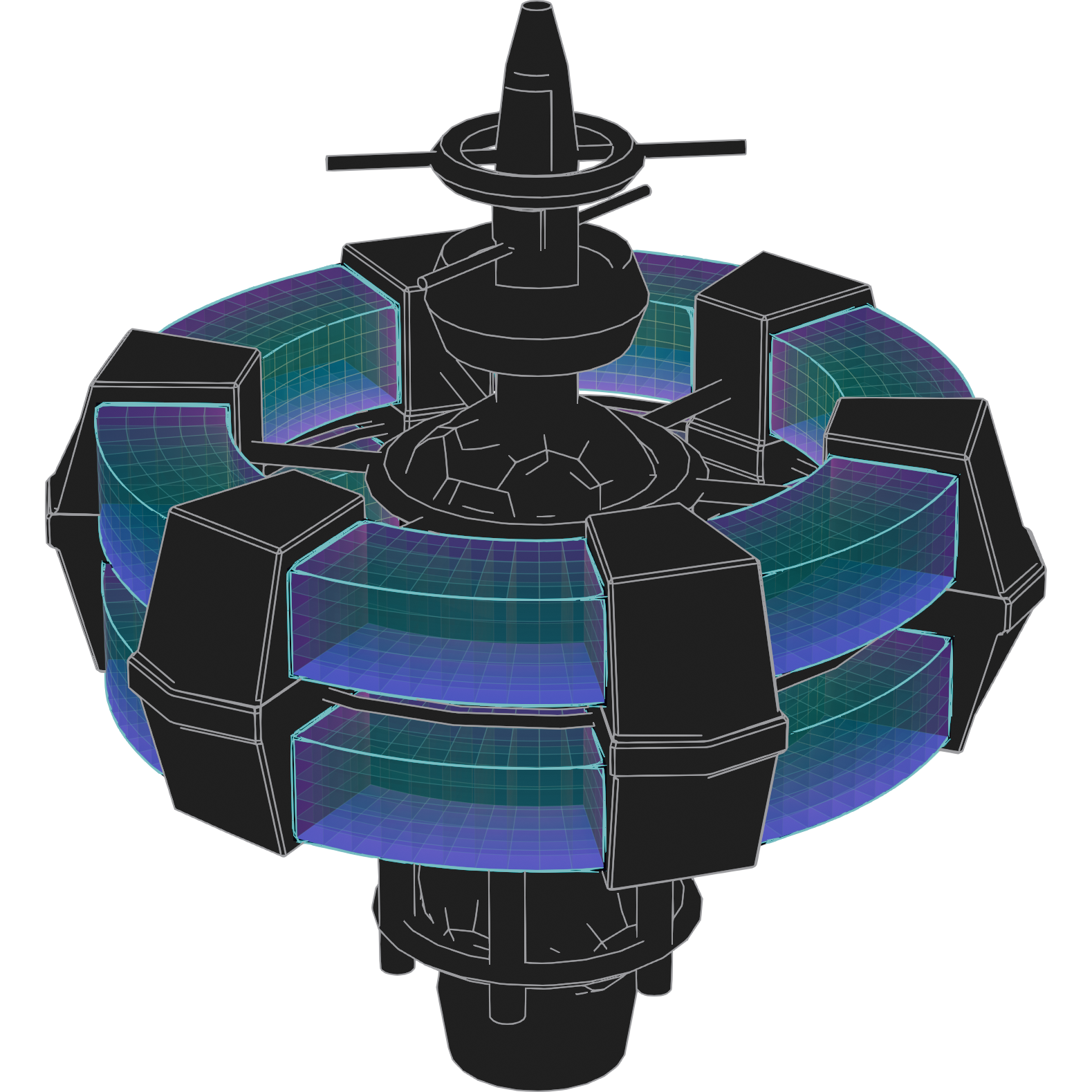
The stretched grid maintains correct proportions but doesn't preserve scale. Frostpunk addresses this issue by adjusting $N_\theta$ relative to the player's building location, effectively managing a series of grids rather than a single one. In our scenario, modules must be directly connected to each other, necessitating the use of a unique grid. Consequently, we opted to limit the grid to an interval that is both narrow in thickness and sufficiently distant from the space station center. This approach helps mitigate the effects of scale dilation within the constrained area of the grid.
BENDING A MODULE
The meshes of the modules will be deformed at runtime via shader to fit within the grid. This deformation involves a combination of bending and stretching, which needs to be computed into the World Position Offset material attribute. Before implementing this inside Unreal Engine's Material Editor, I prefer to rigorously define the equations and parameters that describe the problem. The graphing calculator on Desmos is an excellent tool for starting with the simplest cases and incrementally adding parameters to develop the general case equations.
The bend deformation is oriented by two axes:
- $\vec{u}$ the longitudinal axis, or main deformation axis (orange on the graph)
- $\vec{v}$ the transversal axis, or secondary deformation axis (green)
The bending deformation can then be expressed as two functions $\mathcal{B}_u$ and $\mathcal{B}_v$ that respectively compute the deformed $u$ and $v$ coordinates:
$$\begin{array}{l@{}l} \mathcal{B}_u\left(u,v\right) {}= \left(r_B-v\right)\sin\left(u/r_B\right) \\ \mathcal{B}_v\left(u,v\right) {}= \left(v-r_B\right)\cos\left(u/r_B\right)+r_B \\ \end{array}$$
Where $r_B$ is the bending radius.
STRETCHING A MODULE
In addition to the bend, the modules have to be stretched along the $\vec{v}$ axis so that the geometry follows the increasing gap between consecutive radii of the grid, and also scaled along $\vec{u}$ to account for the spatial dilation of the polar grid. Again, Desmos is useful to figure out equations that work for any position of the modules' pivot point. Similarly to the bending deformation, we can define the stretching functions $\mathcal{S}_u$ and $\mathcal{S}_v$:
$$\begin{array}{l@{}l} \mathcal{S}_u\left(u,v\right) {}= A^\rho u \\ \mathcal{S}_v\left(u,v\right) {}= r_0 A^\rho \left(1-A^{-v/l_0}\right)\\ \end{array}$$
With:
$$A=1+\dfrac{2\pi}{N_\theta-\pi}$$
$$\rho = \dfrac{\ln\left(r_P/r_0\right)}{\ln\left(A\right)}$$
$r_P$ the radius value at the
pivot point of the module
IN ENGINE INTEGRATION
After working out the mathematics, translating the deformation equations into blueprints is pretty easy.
The deformation shader is structured like so:
- Rotate the $\vec{x}$ and $\vec{y}$ local axes so that they match with the deformation axes $\vec{u}$ and $\vec{v}$
- Compute the Stretching: $u \leftarrow \mathcal{S}_u\left(u,v\right)$ and $v \leftarrow \mathcal{S}_v\left(u,v\right)$
- Compute the Bending: $u \leftarrow \mathcal{B}_u\left(u,v\right)$ and $v \leftarrow \mathcal{B}_v\left(u,v\right)$
- Subtract the $u$ and $v$ initial values to get the offsets
- "Un-Rotate" the $\vec{u}$ and $\vec{v}$ axes to line them up with the local $\vec{x}$ and $\vec{y}$ axes
- And transform local coordinates to World coordinates
The shader is used in addition to an Actor BP that does the following:
- Aim the actor's $\vec{y}$ at the center of the world
- Rotate the mesh by a multiple of $90^{\circ}$
- Update the rotation value in the shader and apply it to the mesh
- Mirror the mesh depending on a boolean variable
GALLERY
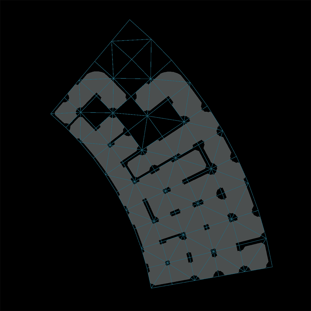
Shader is ready for programmers to code a full construction mechanic
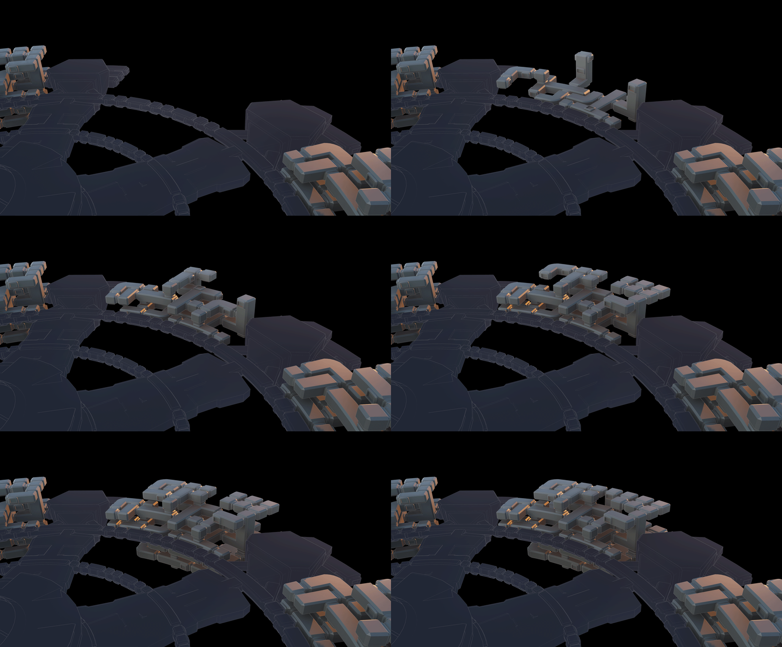
Visual development and concepts are made easier for the artists
